EN
EN

Key Technical Points for Bending Forming Hot Dipped Galvanized Steel
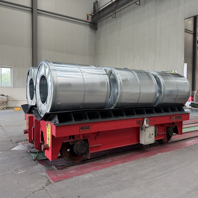
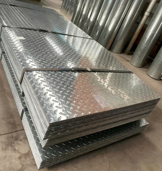
Hot dipped galvanized steel is one of the most widely used coated steel products in construction and fabrication. It is also one of the more commonly mishandled materials when it comes to bending and forming. Most fabricators who have worked extensively with GI coil will tell you the same thing: the rules that apply to cold-rolled bare steel do not automatically transfer to hot dipped galvanized material. The zinc-iron alloy layer changes the equation. Often the difference only becomes clear after you have seen a cracked coating on a finished part.
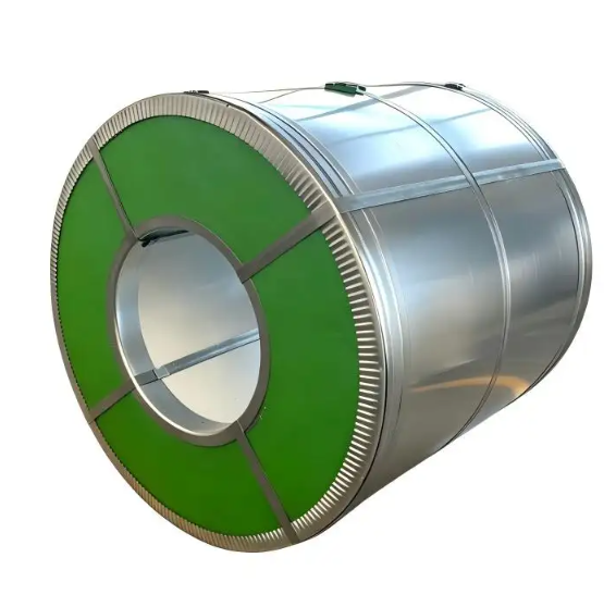
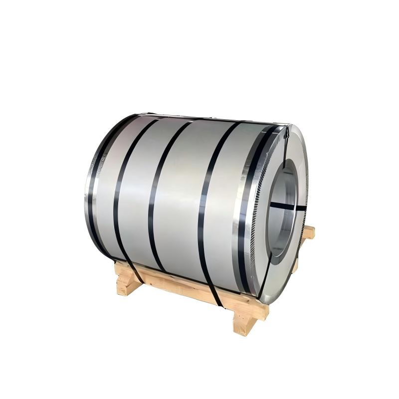
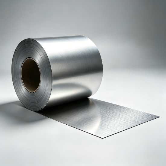
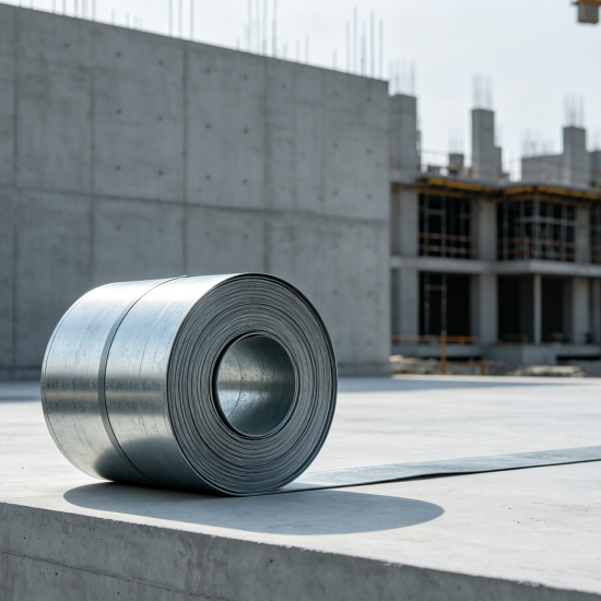
This article covers the technical points that matter most when bending or forming hot dipped galvanized steel coil — from grade selection and coating weight to minimum bend radius standards and post-forming edge treatment. Whether you are specifying formable GI coil for roll-forming lines or managing precision cut GI coil for structural components, these fundamentals apply.
How the Zinc Coating Structure Affects Formability
Unlike electroplated zinc coatings, the zinc layer on hot dipped galvanized steel is not a single uniform metallic film. During the hot dipping process, steel is immersed in a molten zinc bath at approximately 450–460°C (842–860°F), which produces a layered structure: an outer layer of free zinc, beneath which sit intermetallic zinc-iron alloy phases (delta, zeta, and gamma layers) bonded to the base metal.
These alloy layers are inherently less ductile than pure zinc or plain steel. When the material is bent, the alloy layers must deform with the base metal. If the bend is too tight or the coating weight too heavy relative to the material thickness, the alloy layers can fracture — producing visible cracks in the zinc surface at the outer radius of the bend. This goes beyond cosmetics: cracked zinc exposes the base steel at exactly the point where forming stress was greatest.
Grade Selection: Not All Formable GI Coil Bends the Same Way
The ductility of the base metal directly determines how well the hot dipped galvanized steel coil can be formed without coating failure. ASTM A653 — the standard specification for steel sheet coated with zinc by the hot-dip process — defines multiple designations based on forming capability:
- CS (Commercial Steel): Suitable for moderate bending; sufficient for simple profiles and standard structural components.
- FS (Forming Steel): Higher ductility; appropriate for roll-formed sections and profiles requiring consistent bend integrity across high production volumes.
- DDS (Deep Drawing Steel) and EDDS (Extra Deep Drawing Steel): Maximum formability for tight bends and complex shapes; typically specified when the fabrication process demands bends tighter than 2t.
One of the more common sourcing mistakes — and one that shows up in fabrication quality issues — is selecting GI coil based on coating weight and thickness alone, without checking the formability designation. When specifying formable GI coil for a roll-forming line producing curved profiles or tight-radius structural channels, confirming the steel grade designation matters as much as the coating specification.
Minimum Bend Radius Standards and Practical Guidelines
ASTM A143/A143M addresses the safeguarding of hot dipped galvanized structural steel products, including requirements related to bending and embrittlement. The American Galvanizers Association recommends a minimum bend radius of three times the material thickness (3t) as the general guideline for maintaining optimal zinc coating integrity during forming.
In practice, the appropriate minimum bend radius depends on several factors:
- Material thickness: Thicker base metal requires greater bend radii to limit strain at the outer zinc layer. A 1.5 mm sheet can tolerate tighter bends than a 3.0 mm sheet for the same coating weight.
- Coating weight class: Heavier coatings — such as Z275 or Z350 — have proportionally thicker intermetallic alloy layers and are more susceptible to cracking at tight bends than lighter coatings such as Z120 or Z180.
- Steel grade: Higher-ductility grades (FS, DDS) can achieve bend radii closer to 1t without coating fracture, while CS-grade material is better kept at 2t–3t.
- Bend direction: Bending with the rolling direction (longitudinal) typically allows tighter radii than bending across the rolling direction (transverse), due to anisotropic ductility in rolled steel coil.
As a working rule: for standard hot dipped galvanized steel coil with Z120–Z275 coating weight and CS or FS designation, a minimum bend radius of 2t–3t is a reliable starting point. For heavier-coated or higher-yield-strength material, 3t should be treated as the floor, not the target.
Bending Sequence: Before or After Galvanizing?
For fabricated structural assemblies, the preferred approach is to complete all bending and forming operations on the base steel before the part is galvanized. This avoids the problem of bending a zinc-coated surface that is already constrained by the intermetallic alloy layers. When bending must be performed after galvanizing — for example, on pre-coated hot dipped galvanized steel coil from a service center — additional precautions apply.
Re-bending galvanized material after partial straightening carries elevated risk. Zinc that has already accommodated deformation in one direction tends to crack when forced to deform again. If straightening and re-bending cannot be avoided, using press brake tooling with a radius-matched lower die and slow bending speed helps reduce peak strain at the zinc surface.
For precision cut GI coil used in structural channels and roll-formed sections, controlling the bending sequence — and confirming with the service center whether the material has been cold-leveled prior to shipment — is worth including in the procurement specification.
Die Tooling and Process Considerations
The condition of press brake tooling affects zinc coating integrity as much as the material specification does. Sharp die edges or worn punch radii concentrate stress at the zinc surface and accelerate coating fracture. Keeping punch radii at or above the minimum bend radius specification for the material is a simple but effective preventive step.
Applying a light lubricant to the zinc surface prior to press brake forming can reduce friction-induced micro-cracking along the bend line. This is especially relevant for heavier-coated material where the intermetallic layers are thicker. The lubricant also helps the die radius bear evenly against the zinc surface rather than skidding under load.
Forming speed is a secondary but real factor. Faster bending cycles increase the dynamic strain rate at the bend, which reduces the effective ductility of the zinc-iron alloy layer. For tight bends on heavier-coated hot dipped galvanized steel, slowing the press cycle rate is one of the lowest-cost process adjustments available.
Edge Treatment After Precision Cutting
When precision cut GI coil is shear-cut, slit, or laser-cut, the zinc coating at the cut edge is severed, exposing bare base metal. This bare edge is the most vulnerable point in the finished part from a corrosion standpoint — particularly in coastal or humid environments where zinc coating weight on the face provides long service life but cut edges underperform significantly.
For applications where long-term corrosion performance at cut edges is required, cold zinc spray or zinc-rich primer applied to shear-cut edges after forming is the standard field remedy. For structural components in aggressive environments, specifying a higher base coating weight (Z275 or Z350) on the original coil provides greater cathodic protection at cut edges through the galvanic action of adjacent zinc — even without edge treatment.
Yuanhe Steel's custom-slit GI coil service allows buyers to specify exact coil widths matched to their forming and cutting requirements, reducing the number of shear cuts required in downstream processing and minimizing the total length of exposed bare edge per finished component.
Sourcing Considerations for Formable GI Coil
Not every GI coil specification carries the same dimensional tolerance. Thickness variation within a coil — even within ±0.03 mm tolerances — can cause inconsistent bend angles across a production run when the material is formed to a fixed stop position.
Buyers sourcing formable GI coil for high-volume operations should confirm the thickness tolerance class, coil edge camber, and flatness rating in the purchase order. These parameters are controllable at the specification stage but difficult to address after the coil arrives.
For buyers working across international standards, GI coil formability grades are defined in ASTM A653 (US market), JIS G3302 (Japanese market), and EN 10346 (European market). The grade designations and minimum elongation requirements differ between standards — confirming which standard your mill test report references ensures you are evaluating the material's forming capability on a consistent basis.
Working with a supplier that can provide multi-standard compliance documentation and mill test reports for each coil heat reduces specification ambiguity, particularly for projects supplying into multiple markets simultaneously.